It is not always possible to make precise adjustments in the final projector position. The alignment phase is best performed when there is good visibility of the entire screen and the adjustment points are easily accessible. After pre-alignment, the projector can be installed in its final position. By fine-tuning a few parameters, the projector can then be adjusted to fit perfectly.
Prerequisites
This procedure assumes that the UST 90° lens is installed and configured in the applicable orientation and that the lens support bottom plate is attached to the bottom of the projector. See procedures:
Position the projector with UST lens in an easy accessible temporally configuration that equals the final setup.
Same environmental conditions.
Same screen size.
Same projection distance (throw).
Power on the projector and display the checkerboard test pattern.
Note: Allow the projector to warm up for at least 30 minutes. This ensures that the optics stabilize, preventing any focus drift after adjustments.
Adapt the image orientation according the configuration of the UST 90° lens. For example: Lens left orientation for projector table mount = Ceiling rear.
Using Pulse OSD: Menu > Installation > Position > Orientation > Ceiling rear.
Using Pulse Prospector: Setup > Position > Projector position > Ceiling rear.
Adjust the horizontal and vertical shift. Aim for the same shift that is required in the final installation.
Using Pulse OSD: Menu > Installation > Optics > Shift
Using Pulse Prospector: Setup > Optics > Optical Shift
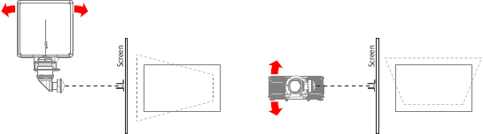
Align the projector and lens exactly perpendicular to the screen. Projected image should be square and level. Proceed as follows:
Project the green focus test pattern.
Ensure that the left and right image height is the same.
If the left side of the image is larger than the right side, the projector is rotated toward the screen. If the right side is larger than the left side, the projector is rotated away from the screen.
Ensure that the top and bottom image width is the same.
A keystone effect is visible if the top of the image is smaller than the bottom, indicating that the projector is leaning toward the screen. In this case, the projector and lens need to be tilted backwards. Conversely, if the top is larger than the bottom, the projector and lens are leaning away from the screen and need to be tilted toward the screen.
Ensure that the image is leveled.
If both the left and right sides of the image are the same height, and the top and bottom are the same width, the projector is correctly squared to the screen. If the image is still not horizontal and level in this case, the projector needs to be leveled front to back, parallel to the screen
Image 5–10
Perform a lens focus calibration.
Caution: Do not calibrate the horizontal and vertical lens shift. The lens is very heavy and the calibration will potentially get stuck.
Using Pulse OSD: Menu > Settings > Maintenance > Lens calibration > Focus
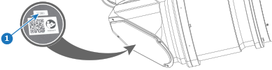
Set the primary motorized focus as close as possible to the reference position (reference 1) indicated on the label on the lens body.
Image 5–11
The current focus position is displayed on screen and LCD when adjusting focus from the lens menu. The outer limits are 0 and 65535.
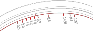
Rotate the barrel of the secondary focus to match the throw distance for the application (distance in meter).
Image 5–12
Check if the depth of field (DoF) area is located behind the projection screen. Move a white paper from the projection screen towards the projection lens and check if the image comes into focus somewhere in between.
If nowhere focused, the DoF lies behind the projection screen. Proceed with the next step.
Adapt the Back Focal Length to gain good focus as follows:
Caution: Do not adjust the primary motorized focus and the secondary manual focus of the lens while adjusting the Back Focal Length. Rotating the Scheimpflug nuts will move the lens holder to where the lens is in focus.
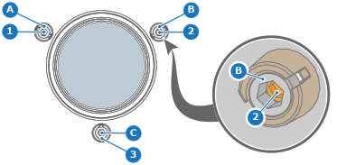
Loosen the three Scheimpflug lock nuts (reference A, B, and C Image 5–13). Use a 5 mm Allen wrench.
Turn each of the three Scheimpflug screws (reference 1, 2, and 3) counterclockwise1/8th of a turn at a time until the top and center of the projected image are in focus. Stop when the focus is good. Use a 4 mm Allen wrench.
Ensure the focus is even between the left and right sides of the projected image by adjusting the left and right Scheimpflug screws (reference 1 and 2). It doesn't need to be perfect, just consistent. If the previous step was done evenly, minimal adjustment should be needed.
Even out the focus at the top and bottom by adjusting the bottom Scheimpflug screw (reference 3). This step corrects for the lens weight. In this configuration, turn the bottom Scheimpflug screw counterclockwise.
Fasten the three Scheimpflug lock nuts. Use a 5 mm Allen torque wrench with a torque of 6 Nm.
Image 5–13
Slightly adjust the primary motorized focus to gain good focus in the center of the projected image.