5.5.5 Adjustment of the UST lens

Note: Because the 90 degrees lens makes use of an intermediate image in the optics of the lens, the projected image will be flipped (top becomes bottom). Because of this, the projector orientation settings have to be adapted accordingly: Ceiling mount becomes Table mount and Front projection becomes Rear projection. See the Pulse OSD user manual or the Pulse Prospector for more info on how to update the projector orientation.
About focus drift and dynamic focus

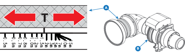
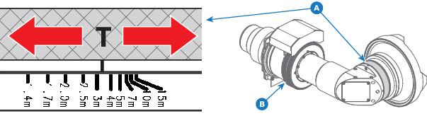
Due to the design of TLD+ lenses and ultra-short throw lenses (UST lenses), these type of lenses tends to heat up over time when used in projectors. This has the side-effect of a slight shift in focus between the lens in its cold state and the lens in its heated state. For this reason it is important to only adjust focus on the mounted lens while it is in its heated state. This can be achieved by projecting an image for 10 minutes or more.

Next to that, content that shifts a lot between dark and bright images can cause the focus to “drift” a little.

While there are external solutions available that perform a “focus drift compensation”, a dynamic focus feature has been implemented that handles this focus drift on projectors that support TLD+ lenses. While enabled, the projector will perform the necessary calculations in order to handle this drift in focus.

Tip: The amount of focus drift can differ between lenses. For that reason it is important to calibrate the focus drift when a new lens is mounted in the projector.

Use the calibration wizard in Pulse Prospector or Projector Toolset to calibrate focus drift. For more info on the focus drift calibration, consult the Pulse Prospector or Projector Toolset user guide.

How to adjust the UST lens
  1. Start up the projector and project the focus pattern on the screen. See pulse OSD user manual for detailed instructions.
  2. Rotate the "adjusting ring for various throw distance" (Ring-A) to the position of the desired throw distance.

    • For example If the throw distance is 1.716 m, the mark should be located between 1.5 m and 2 m. (as shown in Image 5–33).
    • For example: If the throw distance is 3.4 m, the mark should be located between 3 m and 4 m. (as shown in Image 5–34).
    Note: Ring-A is not motorized. Manual adjustment is needed.
  3. Rotate "the focusing gear" (Ring-B) to get good focus in the center of the image.

    Note: Ring-B is motorized. Use the remote control or local keypad of the projector to adjust.
    Image 5–33
    A
    Adjustment Ring-A: various throw distance
    B
    Adjustment Ring-B: focusing gear
    T
    Throw distance (projection distance)
    Image 5–34
    A
    Adjustment Ring-A: various throw distance
    B
    Adjustment Ring-B: focusing gear
    T
    Throw distance (projection distance)
  4. When unable to get a good focus in both the center and corners of the projected image, rotate Ring-A in the direction which results in better focus of the corners.
  5. Rotate the Ring-B again to get good focus in the center of the image.
  6. Repeat the previous steps until a good focus is achieved, both in the center and the corners of the projected image.