5.3 Electronic convergence

Location and availability
About convergence

Convergence alignment of the red, green and blue can drift due to multiple reasons. There are two ways to compensate for this drift:

Note: Electronic convergence can only be used to align up to two pixels in each direction in increments of one pixel. For a more refined convergence method, use the mechanical convergence instead.

For more info on the mechanical convergence, consult the service manual of the projector.

About the convergence test pattern

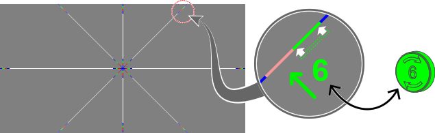
The convergence test pattern consists of horizontal and vertical center lines, as well as two diagonal lines. It features three red arrows numbered 1 to 3, and three green arrows numbered 4 to 6. These numbers and colors correspond to the extended control knobs found on the light processor of the projector. The direction of each arrow indicates the movement of the channel color (red or green) when turning the corresponding control knob in the direction indicated by the arrow on the knob.
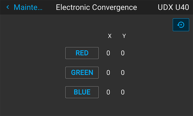
Image 5–15 Convergence test pattern.
Note: Depending on the projector model the convergence test pattern may be slightly different, but the principle remains the same.
How to adjust convergence electronically
  1. Project the Convergence test pattern.
  2. In the Maintenance menu, select Electronic convergence.

    Image 5–16 Maintenance menu, electronic convergence

    The Electronic Convergence menu is displayed.

    Image 5–17 Example of the electronic convergence menu
  3. Select the desired X or Y value for one of the three colors and confirm.
  4. Use the arrow keys to raise or lower the value and confirm.
  5. Repeat all steps until the desired alignment is achieved.
Tip: Press the Reset icon to return all values to the factory settings.