General
The source input panel is located at the back of the projector. For source specifications, see table below.
| Name | Pcs | Description | Purpose |
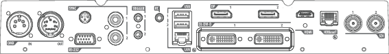
| DMX IN | 1 | DMX 512 input | For Projector Control |
| DMX OUT | 1 | DMX 512 output | For Projector Control |
| RS-232 | 1 | 9–pin DB9 connector | For Projector Control. Allows for wired remote control and monitoring of many projector functions used in installation environments |
| Sync | 3 | BNC Sync Port IN/OUT; Bidirectional mini-DIN (1x 3D sync Out, and 2x Sync In/Out) | For Projector ControlThis is mainly used in multiple projector installations with requirement of synchronization between the units |
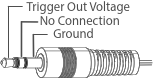
| Trigger | 3 (one in front, two on rear panel) | 12VDC - 0,5A (6W)
| For Controlling Peripherals, like motorized screens, curtains etc. Give 12V output when activated. See API manual for activation info. NOTE Disconnect the projector power cable before connecting or removing the trigger cable. |
| RC | 1 | Jack connector for wired remote | For Projector Control |
| USB | 3 | USB 2.0 type A, 4 pin( 2x Rear and 1x Front) | For Software upgrade |
| LAN | 1 | Standard RJ45 connector | For Projector Control |
| DP | 2 | Standard display port | For Projector Input |
| DL-DVI-D | 2 | Dual DVI-I 1.0 (DVI_D Functionallity). | For Projector Input. These connectors can also be used to form one uniform image by feeding half of the image into each connector. HDCP compliant for sources up 165 Mhz |
| HDMI | 1 | Standard HDMI 2.0 | For Projector Input |
| HDBaseT | 1 | Standard RJ45 8P8C Connector | For Projector Control |
| SDI | 2 | SDI1 is Input, SDI 2 is pass through. (out) | For Projector Input |