Required tools
- Allen key, hex size 4
- Allen key, hex size 6
Distance from lens to the screen during Scheimpflug adjustment.
| Lens | Distance |
| EN64* | 3,0 m |
| EN76* | 2,5 m |
| All other approved lenses* | 2,0 m |
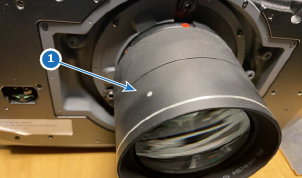
* With one of these lenses installed, ensure that the white dot (reference 1) on the focus ring is oriented 60 degrees counterclockwise from vertical.
Prepare the test area. Barco recommends a projector-screen according to the table “Lens distance” above to be used for all Scheimpflug adjustments.
Verify that the throw ratio of the installed lens matches the requirements of the installation area (projection distance and screen size).
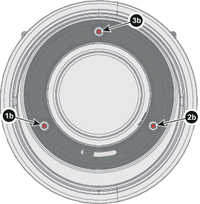
Loosen the three set screws (reference 1b, 2b, 3b). Use a size 6 hex key to do this.
Adjust the left side Scheimpflug adjustment screw (reference 1 in the next figure) until the test image in the top left side of the screen is in focus. Use a size 4 hex key to do this.
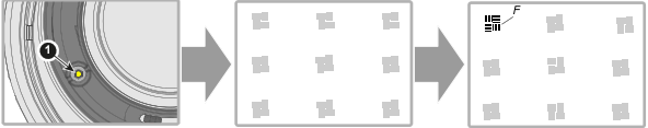
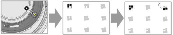
Adjust the right side Scheimpflug adjustment screw (reference 2 in the next figure) until the test image in the top right side of the screen is in focus. Use a size 4 hex key to do this.
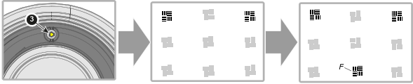
Adjust the top Scheimpflug adjustment screw (reference 3 in the next figure) until the test image in the bottom half of the screen is in focus. Use a size 4 hex key to do this.